Lets Make Tech

EMG Motor Control Using An Arduino.

To get an idea of what this does I made a short video. In this video I am using a PIC18F4520, but an arduino or whatever you have laying around works fine too.


If you are wondering what the signal looks like I printed out the values onto a LCD display and have an oscilloscope reading as well in this video:


First we will need to build our EMG sensor.

First gather up everything that you need.

BOM (For EMG Sensor)                    

1X RR-ST-MTO-DI         
1X ULN2003                 
2X OPA2604A               
1X INA114AP                
1X PIC18F4520             
1X Shielded cable          
2X Alligator Clips (Two double sided wires or just three of the actual clips)           
1x IM414                     
3x T716 Electrode (Bag of disposable electrodes or three reusable ones)         
3x 9 volt battery clip      
1x 10 k resistor             
2x 220 resistor              
2x 1K resistor               
1x 1M resistor               
1x 100 resistor              
1x 47k resistor              
2x 4.7K resistor                        
2x .01 uf capacitor        
1x 4.7 uf capacitor        
1x 10 uf capacitor         
1x 1N5817 diode           
1x 1N5231B diode         


Here is an image of the schematic for it taken from the schematic used in the PIC project.

To prevent confusion I removed the PIC portion of the schematic, hence why it is jagged. 

One of the capacitors on this schematic is not labeled, it is 4.7uf. 

The white circles are electrodes.

The square around two of the electrode wires means that the cable should be shielded. 

I write -9 and +9 however your voltage will be lower. Just consider these positive and negative power supplies. Also not that negative in this case is not referring to ground. 


To make your power source take two 9V battery clips. Solder together positive on one clip with ground on the other clip. This will be ground. The positive wire left will be your positive source and the negative wire left will be your negative source. This will drop the voltage to lower than 9V, don't worry about it it is expected. Please check to make sure that your power source gives you positive, ground, and negative with your multimeter before attaching it to anything.   

undefined


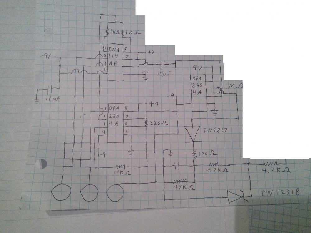
Most EMG circuits give a very noisy signal, this circuit uses filters to give a very clean and smooth circuit that works great for this project. Other projects you may not want to filter and just get the raw signal. To do this remove the 10uf capacitor and everything after it. You may want to adjust the gain using the the resistors on pins 1 and 8 of your instrumentation amp.


Alright the hard part is over and you have a hopefully working EMG lets test it.

1. Take the wire that ends right after the 4.7 kohm resistor and hook it up to an oscilloscope. Also hook ground up to the oscilloscope.

2. Take electrode that connected to your op amp instead of the instrumentation amp and put it on the bony part of the back of your forearm just below your elbow.

3. Place one of the other electrodes on the top/middle of your bicep.

4. Place the other electrode on the bottom of your bicep near where your forearm is about to begin.

5. Look at the signal when flexing your arm, if the signal isn't there check your connections and that you have batteries hooked up. Make sure that when flexing as hard as you can your signal does not exceed 5V. The circuit above should prevent this, but better safe than sorry.

6.If it is safe and working how you want proceed, if not feel free to make any alterations you want. 


Get your stepper motor set up.

 I recommend getting a stepper motor that is 5V so that you can run it from the Arduino and also getting one that comes with a driver although you can use whatever you want.

I used the RioRand Stepper Motor 5V DC 4-Phase 5-Wire with ULN2003 Driver Board. It will only set you back about $8.00 USD

It needs 4 pins to go from the Arduino to the driver, then hook it up to 5V and ground. Simple. 


Code

Stepper Control 


void forward()
{
digitalWrite(A, HIGH);
delay(2);
digitalWrite(B, HIGH);
delay(2);
digitalWrite(A, LOW);
delay(2);
digitalWrite(C, HIGH);
delay(2);
digitalWrite(B, LOW);
delay(2);
digitalWrite(D, HIGH);
delay(2);
digitalWrite(C, LOW);
delay(2);
digitalWrite(A, HIGH);
delay(2);
digitalWrite(D, LOW);
delay(2);
digitalWrite(A, LOW);
delay(2);
steps++;
}

void reverse()
{
digitalWrite(A, HIGH);
delay(2);
digitalWrite(D, HIGH);
delay(2);
digitalWrite(A, LOW);
delay(2);
digitalWrite(C, HIGH);
delay(2);
digitalWrite(D, LOW);
delay(2);
digitalWrite(B, HIGH);
delay(2);
digitalWrite(C, LOW);
delay(2);
digitalWrite(A, HIGH);
delay(2);
digitalWrite(B, LOW);
delay(2);
digitalWrite(A, LOW);
delay(2);
steps--;
}


Read the signal from the EMG pin, convert it into the new step you want your motor to be in, keep track of your current step, go in the direction of the new step.


 Use the serial monitor see what kind of range you get from an analog read of the EMG in Pin. Very relaxed it was 0-13. Fully flexed it was about 600-800. Relaxed but moving my arm straight to bent it would go from 0 to 200.

This number is arbitrary and may be different for you. I use it to make my new step. I keep track of my current step and if it doesn't match the new step i move in the direction it needs to go.


So, here is the complete code. It is pretty basic but gives you a reference point on how to get started. I recommend making a multi-channel EMG and comparing the bicep to the triceps to get a more accurate idea of your arm's position. 


const int A = 12;
const int B = 11;
const int C = 10;
const int D = 9;
const int EMG = A0;

int steps = 0;
int newstep = 0;
float signal;
void forward();
void reverse();
void setup()   /*----( SETUP: RUNS ONCE )----*/
{
  pinMode(A, OUTPUT);
  pinMode(B, OUTPUT);
  pinMode(C, OUTPUT);
  pinMode(D, OUTPUT);  
  pinMode(EMG, INPUT);
  Serial.begin(9600);
}

void loop()   /*----( LOOP: RUNS CONSTANTLY )----*/
{
    signal=analogRead(EMG);
    Serial.print(" Newstep: ");
    Serial.print(newstep);
    Serial.print(" Step:");
    Serial.print( steps);
    newstep=signal;
    if (newstep<steps)
    {
      reverse();
    }
    if (newstep>steps)
    {
      forward();
    }

}
void forward()
{
    digitalWrite(A, HIGH); 
    delay(2);   
    digitalWrite(B, HIGH);
    delay(2);
    digitalWrite(A, LOW);
    delay(2);
    digitalWrite(C, HIGH);
    delay(2);
    digitalWrite(B, LOW);
    delay(2);
    digitalWrite(D, HIGH);
    delay(2);
    digitalWrite(C, LOW); 
    delay(2);
    digitalWrite(A, HIGH);
    delay(2);
    digitalWrite(D, LOW);
    delay(2);
    digitalWrite(A, LOW);
    delay(2);
    steps++;
}

void reverse()
{
    digitalWrite(A, HIGH);
    delay(2);
    digitalWrite(D, HIGH);
    delay(2);
    digitalWrite(A, LOW);
    delay(2);
    digitalWrite(C, HIGH);  
    delay(2);     
    digitalWrite(D, LOW); 
    delay(2);
    digitalWrite(B, HIGH);
    delay(2);
    digitalWrite(C, LOW);  
    delay(2);
    digitalWrite(A, HIGH);
    delay(2);
    digitalWrite(B, LOW);
    delay(2);  
    digitalWrite(A, LOW);
    delay(2);
    steps--;
}


Have fun, if you make something cool be sure to share in the comments.

Signal Generator

I threw this together real quick to test out a signal generator and it is a bit sloppy and written around someone else's code (their code isn't sloppy mine is). This code should just be used as a reference or for testing and credit given to David Mills for the part of the code that I borrowed from him.

This tutorial shows how to make a signal generator using the AD9850 DDS signal generator, an Arduino, and a potentiometer. I used code written by David Mills http://webshed.org/wiki/AD9850_Arduino to interface with the signal generator and added to it to allow you to set the frequency using a potentiometer and change the mode between Hz, kHz, and MHz by pressing a button. As David Mills requested, don't claim the code as your own or try to prevent anyone else using it other than that do with it what you will. 

If you are interested in making music with this check out this previous post.

BOM

-1 Arduino

-1 LCD display (optional)

-1 AD9850 DDS signal generator

-1 Touch button

Connections

Note the connections between the arduino and the AD9850 DDS signal generator. Feel free to change them if you need.

#define CLOCK 2 //pin connections for DDS
#define LOAD 3
#define DATA 7
#define RESET 8

For the LCD I used the following connections LiquidCrystal lcd(5, 6, 9, 10, 11, 12); For additional help connecting the LCD see this tutorial

Note that in this tutorial they use different pins and it uses a potentiometer being used on pin 3, I just used a resistor to ground. The value will vary between screens and it is just used to set contrast. If your screen is all black or white you may need to use a different resistor or adjust the pot. 


For the pot and button I used the following pins

#define POTPIN A0
#define MODE 13


Use the button to change the mode, then depending on what mode it is, change how you interpret the pot.

Interpreting the pot, convert the reading from the pot to a value between 0 and 1,000 for mode 1, 1,000-1,000,000 for mode 2, and 1,000,000-30,000,000 for mode 3. You will want to limit it to 30,000,000 because past that the hardware doesn't work. You may need to edit the code I used for the potentiometer that you use.

Send this to the AD9850 DDS signal generator using the code that David Mills wrote.

Pro tip: Display the frequency and mode on the LCD so you know what you are doing. 

Alternative inputs: The potentiometer I used wasn't very accurate and the value changed a lot when set all the way up or down. Use buttons or a keypad to set the frequency to get an exact amount and easily set it how you want.   


The complete code:

#include <LiquidCrystal.h>

LiquidCrystal lcd(5, 6, 9, 10, 11, 12);


#define DDS_CLOCK 125000000

#define  CLOCK  2  //pin connections for DDS
#define  LOAD 3 
#define  DATA  7
#define  RESET 8
#define  POTPIN A0
#define  MODE 13
float hrz;
float pot;
float temp;
int mode=0;
int moderead;
void setup()
{
  pinMode(DATA, OUTPUT); 
  pinMode(CLOCK, OUTPUT); 
  pinMode(LOAD, OUTPUT); 
  pinMode(RESET, OUTPUT); 
  pinMode(POTPIN, INPUT);
  pinMode(MODE, INPUT);
  AD9850_init();
  AD9850_reset();
  lcd.begin(16, 2);
  Serial.begin(9600);
  
  //SetFrequency(hrz);

}

void loop()
{ 
 moderead=digitalRead(MODE); 
 pot=analogRead(POTPIN);  //14-1000
 hrz=((pot-6)*10000000); 
 if (moderead==LOW)
 {
   mode++;
   delay(500);
   if (mode>2)
   {
     mode=0;
   }
 }
 
 if (mode==0)
 {
   hrz=(hrz/10000000);
    lcd.setCursor(0, 1);
    lcd.print("MODE: Hz");

 }
 
 if (mode==1)
 {
   hrz=(hrz/10000);
    lcd.setCursor(0, 1);
    lcd.print("MODE: KHz");
 }
 
 if (mode==2)
 {
    hrz=(hrz/100);
    lcd.setCursor(0, 1);
    lcd.print("MODE: MHz");
 }
if (mode!=3)
{
 if (hrz<0)
 {
   hrz=0;
   
   if (temp>1000)
   {
     lcd.clear();
   }
   lcd.setCursor(0, 0);
   lcd.print(hrz,1);
   lcd.print("HZ   ");
 }
 
 if (hrz>0 && hrz<1000)
 {
   if (temp>1000)
   {
     lcd.clear();
   }
   lcd.setCursor(0, 0);
   lcd.print(hrz,1);
   lcd.print("HZ   ");
 }
 if (hrz>1000 && hrz<1000000)
 {
   if (temp<1000|| temp>1000000)
   {
     lcd.clear();
   }
   lcd.setCursor(0, 0);
   lcd.print(hrz/1000,1);
   lcd.print("KHZ   ");
 }
  if (hrz>1000000 && hrz<30000000)
 {
   if (temp<1000000)
   {
     lcd.clear();
   }
   lcd.setCursor(0, 0);
   lcd.print(hrz/1000000,1);
   lcd.print("MHZ   ");
 }
 if (hrz>30000000)
 {
   hrz=30000000;
   if (temp<1000000)
   {
     lcd.clear();
   }
   lcd.setCursor(0, 0);
   lcd.print(hrz/1000000,1);
   lcd.print("MHZ   ");
 }
 
 
 SetFrequency(hrz);
 temp=hrz;
} 

}
void SetFrequency(unsigned long frequency)
{
  unsigned long tuning_word = (frequency * pow(2, 32)) / DDS_CLOCK;
  digitalWrite (LOAD, LOW); 

  shiftOut(DATA, CLOCK, LSBFIRST, tuning_word);
  shiftOut(DATA, CLOCK, LSBFIRST, tuning_word >> 8);
  shiftOut(DATA, CLOCK, LSBFIRST, tuning_word >> 16);
  shiftOut(DATA, CLOCK, LSBFIRST, tuning_word >> 24);
  shiftOut(DATA, CLOCK, LSBFIRST, 0x0);
  digitalWrite (LOAD, HIGH); 
}

void AD9850_init()
{

  digitalWrite(RESET, LOW);
  digitalWrite(CLOCK, LOW);
  digitalWrite(LOAD, LOW);
  digitalWrite(DATA, LOW);
}

void AD9850_reset()
{
  //reset sequence is:
  // CLOCK & LOAD = LOW
  //  Pulse RESET high for a few uS (use 5 uS here)
  //  Pulse CLOCK high for a few uS (use 5 uS here)
  //  Set DATA to ZERO and pulse LOAD for a few uS (use 5 uS here)

  // data sheet diagrams show only RESET and CLOCK being used to reset the device, but I see no output unless I also
  // toggle the LOAD line here.

  digitalWrite(CLOCK, LOW);
  digitalWrite(LOAD, LOW);

  digitalWrite(RESET, LOW);
  delay(5);
  digitalWrite(RESET, HIGH);  //pulse RESET
  delay(5);
  digitalWrite(RESET, LOW);
  delay(5);

  digitalWrite(CLOCK, LOW);
  delay(5);
  digitalWrite(CLOCK, HIGH);  //pulse CLOCK
  delay(5);
  digitalWrite(CLOCK, LOW);
  delay(5);
  digitalWrite(DATA, LOW);    //make sure DATA pin is LOW

    digitalWrite(LOAD, LOW);
  delay(5);
  digitalWrite(LOAD, HIGH);  //pulse LOAD
  delay(5);
  digitalWrite(LOAD, LOW);
  // Chip is RESET now
}


Newer posts → Home ← Older posts